


Fiber Optic Tech
Types of Tunable Optical Filters (TOFs)
Tunable Optical Filters (TOFs), along with tunable lasers, are recognized as the two most critical optical devices in optical communication networks and systems. With the increasing number of Dense Wavelength Division Multiplexing (DWDM) channels, achieving narrow-bandwidth filtering and high-power laser output has become a research hotspot.
In recent years, there are more and more types of optical filtering technologies. TOFs made by different technologies have developed from the initial TEF type and F-P cavity type to acousto-optic tunable filter (AOTF) type, micro-ring resonator type, photonic crystal type, fiber grating type, etc.
Thin-Film Filter (TFF)
Dielectric Thin-Film Filter (TFF) technology is the most mature wavelength division multiplexing technology after the commercialization of WDM systems. The core of this technology lies in the dielectric thin-film filter. The working principle of a TFF-type TOF is: coating on a glass substrate, and the function of the multilayer film is to make light generate interference for frequency selection. The dielectric film optical filter has a strong dependence on the preparation of the filter. The development of thin-film technology has become the main factor restricting the development of this filter. In particular, the stress effect of up to 200 layers of film system on the substrate and the influence of substrate thickness, type, and linear expansion coefficient on the key indicators of the device's passband ripple, dispersion, etc. are very large.
Currently, the key technical challenges of TFF optical filters lie in improving the device isolation and reducing the device polarization dependence. A common method to improve isolation is to use the cascade of multiple FP cavities to achieve a flat passband for filtering. The more FP cavities, the better the rectangularity of the filtered waveform. However, the negative impact of multi-cavity filters is that the ripple increases with the number of cavities, which will directly affect the power stability of the output light. In response to this, a detailed analysis of the reflectance matching conditions for the superposition of different numbers of cavities was carried out, and matching was achieved by adjusting the reflectance of the middle FP cavity with the reflectors of each cavity on both sides. The problem of depolarization of TOFs has been extensively studied in recent years. By using the thin-film matrix algorithm to mix materials with high and low refractive indices in the spacer layer of the filter, the center wavelength of the aligned polarized light is obtained. Through the characteristic matrix, the refractive index materials that satisfy the same reflectance of different polarized light are found, and the bandwidth overlap of polarized light is realized.
F-P Cavity Type
F-P cavity-type tunable filters have advantages such as high finesse, fast tuning speed, and compact size, making them widely used in optical fiber communication systems. Currently, F-P cavity filters come in various types, including MEMS-based F-P cavity filters, fiber-based F-P cavity filters, and liquid crystal-based F-P cavity filters.
The main principle of fiber-based F-P cavity filters involves polishing the fiber end face and coating it with a high-reflectivity film. The air gap between the fiber end faces serves as the F-P cavity, and the cavity length is adjusted through the piezoelectric effect.
Liquid crystal-based filters achieve tuning by injecting current, which changes the spatial orientation of liquid crystal molecules inside the cavity via the electro-optic effect. This alters the extraordinary refractive index of the liquid crystal molecules. These optical filters have a simple structure and a wide tuning range but are sensitive to temperature and prone to polarization effects caused by the birefringence of liquid crystal molecules.
Micro-mechanical tuning has seen rapid development in recent years. MEMS-based optical filters utilizing this principle employ electrostatic or thermal actuation to induce mechanical displacement of the mirrors, thereby altering the length of the piezoelectric ceramic material to achieve cavity length adjustment.
Based on MEMS technology, the tunable optical filter (TOF), as shown in Figure 1, achieves wavelength tuning by adjusting the rotation angle of a tunable diffraction grating via a micro-mechanical system. It supports operation in the C or L bands and can be applied in optical channel monitoring, optical spectrum analysis, and various other fields.
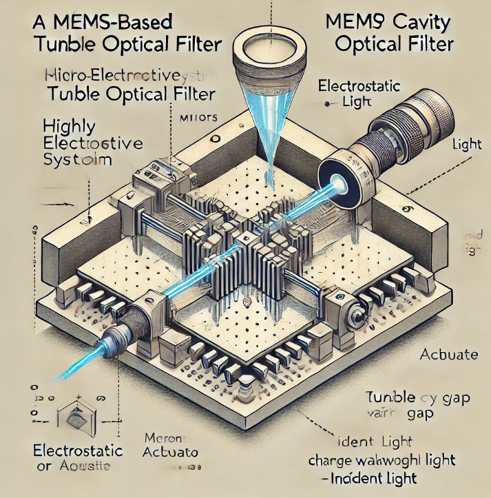
Figure 1. Schematic Diagram of a MEMS-Based F-P Cavity Filter
Acousto-Optic Tunable Filter (AOTF)
The Acousto-Optic Tunable Filter (AOTF) is not affected by mechanical tuning precision, making it a highly promising filter for use in Dense Wavelength Division Multiplexing (DWDM) systems.
Its main principle is based on the normal acousto-optic effect in an isotropic medium, where elastic deformation caused by ultrasonic waves leads to periodic changes in the refractive index of the medium. The medium through which the ultrasonic waves propagate acts as a "grating" to filter the incident light.
However, to manufacture a high-performance tunable optical filter (TOF), an anisotropic medium must be used. In this case, the interaction between surface acoustic waves (SAWs) and optical waves induces anomalous Bragg diffraction. This diffraction alters the polarization state of the incident light that satisfies the phase-matching (Bragg diffraction) condition. Together with a polarization controller, this process forms the filter, thereby achieving optical filtering.
The key technical challenges of AOTF currently lie in suppressing the sidelobe effect and addressing polarization dependence. Due to the influence of acoustic wave intensity distribution, the traditional single-stage polarization-dependent collinear AOTF exhibits sidelobes around -9 dB in its transmission spectrum, with a 3 dB bandwidth of approximately 1.6 nm, making it unsuitable for narrowband filtering.
In recent years, several methods have been developed to suppress sidelobes, including weighted coupling, birefringence, and cascading. Weighted coupling suppresses sidelobes by adjusting the acousto-optic coupling coefficient, and by optimizing a Gaussian weighting function, the sidelobes can be reduced to -41 dB. Birefringence apodization suppresses sidelobes by modifying the birefringence along the optical waveguide direction, and methods based on this approach can reduce sidelobes to approximately -30 dB. Multistage filtering achieves sidelobe compression by cascading multiple single-stage devices.
Polarization dependence is a critical issue for AOTF. One solution is the polarization-independent integrated acousto-optic tunable filter (IAOTF), which operates by separating TE and TM modes into different waveguides using two mode splitters and then coupling them at the output, as shown in Figure 1. Additionally, AOTF employs a to minimize polarization-dependent loss (PDL). To eliminate polarization dependence, AOTF utilizes acoustic torsional wave coupling to manipulate polarization modes.
Acousto-optic tunable optical filters (AOTFs) have already been commercialized. They can operate over an optical spectrum range of up to one octave, with a resolution of a few nanometers in the visible spectrum, and their sidelobes can be suppressed below -20 dB.
The AOTF series enables rapid tuning across the entire spectral range and is widely used in spectrometers, dispersion applications, and other fields. The operating wavelength range extends from 0.34 to 4.5 microns.
Fiber Bragg Grating Type
Fiber Bragg Grating (FBG) filters are a popular technology in the field of photonics research. In Wavelength Division Multiplexing (WDM) systems, fiber Bragg gratings utilize the photosensitivity of optical fiber materials—where the interaction between externally incident photons and germanium ions in the fiber core induces a permanent change in the refractive index. This process creates a spatial phase grating within the core. The wavelength that satisfies the Bragg grating condition (λ = 2nΛ, where Λ is the grating period) is reflected, while other wavelengths are transmitted. This effectively forms a narrowband filter within the fiber core, as illustrated in Figure 2.
Since fiber Bragg gratings are sensitive to temperature and pressure, tuning is typically achieved by adjusting the grating period through thermal or pressure control. FBG filters can be directly spliced into the system, and by inscribing the grating using an ultraviolet light source, the reflectivity of the reflected light can reach nearly 100%. Their wavelength, bandwidth, and dispersion can be flexibly controlled, resulting in a highly rectangular spectrum and excellent filtering characteristics.
However, when FBG filters are applied in multi-channel systems, a large number of FBGs are required if a cascaded structure is used for wavelength separation. To reduce the number of FBGs, these filters often adopt a combining an FBG with a circulator. While this approach helps optimize FBG usage, it introduces additional insertion loss and increases overall system costs.
Currently, sidelobe crosstalk and tuning range are important factors that must be considered in the development of fiber Bragg grating (FBG) filters. Since FBGs are made of quartz, which has a high elastic modulus, their wavelength tuning range is limited to only 0.01 nm when using conventional tuning methods. To achieve tuning over the C-band, an extremely large temperature variation would be required, which is impractical for real-world applications.
To address these issues, current solutions involve modifying the tuning structure and designing apodization functions.
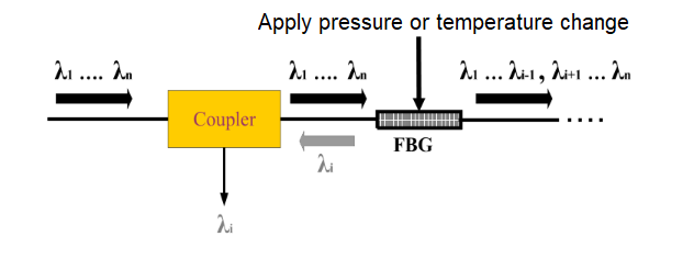
Figure 2 Schematic Diagram of Fiber Bragg Grating TOF
Microring-resonant
Microring resonators are a current research hotspot, as they can be used to implement various functional devices. They offer advantages such as compact structure, high-quality factor, and small component size, making them suitable for large-scale integrated circuits. Research institutions have already demonstrated the feasibility of fabricating optical devices with more than 100 coupled microrings.
Compared with other optical filters, microring resonator-based filters provide greater flexibility for spatial channel separation. In a single-ring resonator, to establish a stable field distribution, the oscillating mode inside the ring must be self-reproducing after one round trip. This requires the phase change to be an integer multiple of 2π, meaning that the output signal fed back into the system must have the same phase as the original input signal. The filtering function is achieved by satisfying the microring resonance equation: m·2π=2πnR (where R is the microring radius, and n is the effective refractive index of the microring waveguide.)
Tuning of microring resonator-based filters is typically achieved through thermal modulation and modification of the microring radius. Additionally, the absorption effect of free carriers can be utilized—by injecting free carriers into the semiconductor, the refractive index can be altered to achieve wavelength tuning.
Microring-resonant filters can be structurally divided into vertically coupled and laterally coupled types. Among them, lateral coupling requires electron beam lithography to precisely control the spacing between the micro-ring and the straight waveguide, while vertical coupling only needs to rely on epitaxial growth to control the coupling coefficient. From the material point of view, they can be divided into insulator type, semiconductor type and polymer type. Among them, the insulator-based micro-ring has small insertion loss, but it is only suitable for passive devices. The semiconductor-based micro-ring is divided into silicon and III-V compounds. Silicon materials have mature technology but cannot provide gain. III-V compound materials have high loss and the technology is not mature enough. The polymer-based micro-ring has a stable structure, simple manufacturing process and low cost, so it is a very promising solution.
Currently, the research focus of micro-ring resonator filters is on multi-ring cascade processes. Since the passband flatness of single-ring filters is not sufficient, this type of filter inevitably develops towards multi-ring cascades. Figure 3 shows a comparison of the filtered spectra with different numbers of rings. As can be seen, when the number of rings increases, the rectangularity of the filtered spectrum becomes better and better. However, multi-ring cascades introduce problems of inter-ring resonance tuning and precise control of coupling coefficients in actual fabrication. Therefore, the step of designing the coupling coefficients between the ring and the straight waveguide, and between the rings is very crucial.
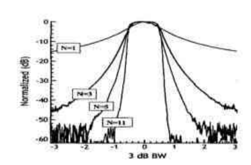
Figure 3 Comparison chart of transmission spectra with different ring numbers.
Photonic Crystal Type
Since its proposal in 1987, the theory and numerical simulation technology of photonic crystals have been developed relatively maturely. Due to the small size of photonic crystals, they are suitable for fabricating tiny integrated optical devices, and are also the development trend of optical filters in DWDM systems. Photonic crystal filters can generate transmission modes in the photonic band gap by introducing defects in the periodic structure of the photonic crystal, thereby realizing the control of light waves. The filtering performance of photonic crystal filters is far superior to that of ordinary optical filters. The suppression of transmitted light in the stop band can easily reach above 30dB, and its band-stop steepness is close to 90 degrees, with excellent rectangularity. In addition, due to the excellent bending effect of photonic crystals, the energy transmission is basically lossless, so the loss of light waves passing through the passband of photonic crystal filters is very small. These advantages have attracted the attention of a large number of research institutions at home and abroad to photonic crystal technology, and the research on using photonic crystals to make tunable filters is even more numerous.
Tunable photonic crystal filters mainly have two forms of tuning: using the change of band gap defects or the change of photonic crystal structure level. Introducing liquid crystal material at the defect of the photonic crystal, combining the liquid crystal with the one-dimensional photonic crystal, and using the photonic band gap, defect characteristics and the characteristic that the refractive index of the liquid crystal changes with the voltage to construct a new type of TOF. When the driving voltage is increased from 0.5V to 5V, the transmission peak shifts from 1520nm to 1552nm, the tuning range reaches 32nm, and the bandwidth is between 0.4-1.7nm. Photonic crystals are called "optical semiconductors" by the scientific community. At present, photonic crystal technology has transitioned from the theoretical research stage to the laboratory stage. It can be expected that in the next few years, various optical devices based on photonic crystals will gradually become commercialized.


