Fiber Optic Tech
Principle and Application of OXC
Optical Cross-Connect (OXC) is a crucial device in optical networking, used to direct optical signals between input and output ports without converting them to electrical signals. OXCs enable efficient, high-speed, and scalable data routing in Dense Wavelength Division Multiplexing (DWDM) and wavelength-routed networks.
Optical fiber itself has huge communication potential, but its bandwidth advantage cannot be brought into play due to the bottleneck of node electronics. The way people solve this problem is to use OXC equipment to exchange directly at the optical level. Because the exchange of light is different from the exchange of electronics, it is not simply named as an optical switch, but an optical cross-connect (Optical Cross Connection) device.
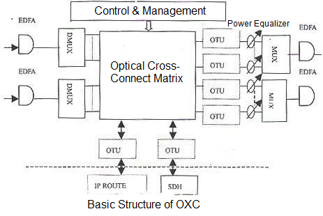
Let’s make a comparison, the difference between OXC and DXC. The traditional DXC (digital cross-link) equipment, such as DXC in SDH, has functions such as signal multiplexing, signal switching, protection switching, monitoring and management; OXC completes these actions at the optical level. At the same time, since OXC does not need to care about the format and rate inside the signal, it can transparently process the lower-level light, making it very versatile, while DXC must deploy corresponding equipment according to different signal formats. In addition, the processing capacity of OXC can reach Petabit (one petabit is equivalent to 10 to the 15th power of binary digits, and one petabit is equal to one thousand gigabits). DXC can only reach the Gigabit level. DXC is mainly composed of five parts: input unit (amplifier EDFA, demultiplexer DMUX), optical cross-connection part (cross-connection matrix), output unit (wavelength converter OTU, power equalizer, multiplexer), control and management unit and its add/drop multiplexing. As shown in the figure:

After amplification and demultiplexing, the optical signal is dispersed into a single wavelength of light waves, which enter the switching matrix for switching, and then the wavelength is changed and the power is equalized before re-multiplexing and output. At the same time, it can also be multiplexed on the IP network and SDH link. Note that the output optical signal at this time has changed from the input optical signal in terms of both user and wavelength. Here, the wavelength change is designed to solve the problem that two optical waves with the same wavelength cannot be multiplexed in the same optical fiber. The power equalizer is designed to ensure that the optical signal power of each wavelength channel is controlled within the allowable range to prevent the non-balanced gain from being amplified by the EDFA and causing a serious nonlinear effect.
The main modules of OXC:
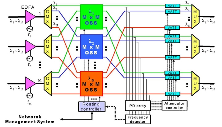
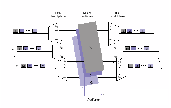
(1) Optical cross-connect matrix. The pure optical cross-connect matrix OXC is still in the stage of research and development and field experiment. One of the main problems is that there is no optical switching matrix with good performance-price ratio, expandable capacity, stable and reliable. The current main development direction is the new optical switch of electromechanical switch (MEMS). The main indicators of the optical switching matrix are polarization independence, high optical channel isolation, low insertion loss, low channel loss, good channel uniformity, and good multi-wavelength operation capability.
(2) Wavelength converter. The wavelength converter can convert signals from one wavelength to another to achieve exchange in the wavelength domain. There are currently two basic methods: optical and all-optical. The optoelectronic hybrid method has excellent performance in terms of power, signal regeneration, wavelength and polarization sensitivity, but it is not transparent to different transmission code formats and bit rates. Therefore, the wavelength converter in the OXC uses an all-optical conversion method.
(3) Erbium-doped fiber amplifier. The function of erbium-doped fiber amplifier (EDFA) is to effectively compensate for line loss and node internal loss, and extend the transmission distance. EDFA has the characteristics of wide bandwidth, transparency to modulation mode and transmission code rate, etc.
(4) Power equalizer. The power equalizer makes the difference of optical power of each wavelength channel within the allowable range, and prevents serious nonlinear effects on the system after cascading EDFAs through multiple nodes.
(5) Control and management unit. The control and management unit implements the control and management of each functional module of the OXC device. It has an automatic protection switching function and can also support end-to-end connection assignment of the optical transport network, dynamically configure wavelength routing, and quickly protect and restore network transmission services.

At the same time, a switching hub composed of multiple OXCs can perform optical cross-connect control with higher scale and finer granularity, thus achieving flexible processing of transport network services.
OADM principle and application
We have learned about the basic principle of OXC and felt its important position in the optical transmission process. Now let's introduce another important device, the optical add-drop multiplexer. Add-drop multiplexing refers to "separating" a wavelength of light from the transmission node or "inserting" the same wavelength of light into it. Using add-drop multiplexing equipment in the optical network can make the wavelength application and al of the optical network more flexible.
The basic functions of OADM include three types: wavelength channels required for drop are multiplexed into the add signal, so that other wavelength channels can pass through as unaffected as possible. The specific working process of OADM is as follows: the optical signal from the line contains multiple wavelength channels, which enter the input end of OADM. According to business needs, the required wavelength channels are selectively output from the drop end (Drop) from multiple wavelength channels, and the required wavelength channels are input from the add end (Add) accordingly. Other wavelength channels that are not related to the local area directly pass through OADM, are multiplexed with the add wavelength channels, and are output from the line output end of OADM.

According to different network designs, business requirements and resource al, optical networks have certain requirements for OADM nodes used in them, mainly focusing on performance requirements, which are specifically reflected in the following aspects: reconfigurability, scalability, transparency and multi-channel processing capabilities. In addition, the introduction of OADM has advantages and disadvantages for network management. Although OADM allows flexible management of optical channels, its flexibility is not completely unconstrained, and the signal degradation caused by OADM needs to be seriously considered. There is a balance point in the technical selection between network goals and the optical performance of OADM.
The main parameters of OADM are: channel spacing, channel bandwidth, center wavelength, channel isolation, wavelength temperature stability, and channel loss uniformity.
The main modules of OADM: The core device of OADM node is optical filter device, which selects the wavelength to be added/dropped to realize wavelength routing. The more mature filters currently used in OADM include acousto-optic tunable filter, volume grating, arrayed waveguide grating (AWG), fiber Bragg grating (FBG), multilayer dielectric film, etc. From the specific form of OADM implementation, it mainly includes two categories: wavelength splitter/combiner plus optical switch array and fiber grating plus optical switch.
(1) Wavelength splitter/combiner plus optical switch array
The wavelength routing of this structure uses a wavelength splitter/combiner, and the through-through and up-down switching of the OADM is realized by an optical switch or an optical switch array. The crosstalk between the branch and the group of this structure is determined by the optical switch, and the crosstalk between wavelengths is determined by the wavelength splitter/combiner. Since the loss of the wavelength splitter/combiner is generally large, the main disadvantage of this structure is the large insertion loss. At present, wavelength splitters and combiners mostly use devices such as body gratings, multilayer dielectric films and arrayed waveguide gratings.
(2) Fiber Bragg Gratings
Fiber Bragg Gratings (FBGs) are optical devices that use ultraviolet light interference to form periodic refractive index changes (gratings) in optical fibers. Its advantages are that it can be directly written into communication optical fibers, has low cost, high production repeatability, can be mass-produced, is easy to connect to various optical fiber systems, has low connection loss, and can flexibly control wavelength, bandwidth, and dispersion. The main problem is that it is greatly affected by the external environment. For example, slight changes in factors such as temperature and strain will cause the center wavelength to drift.
The difference and application of OXC and OADM
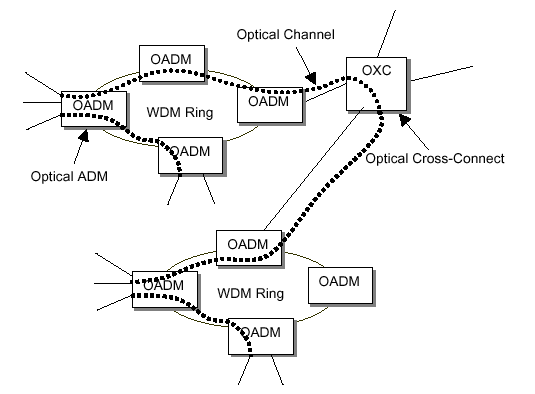
In general, OXC and OADM are both indispensable and important components of optical networks, and there is no difference in status. However, in terms of composition and attributes, OADM is actually a special implementation of OXC. Simply put, OXC contains OADM, and in today's network, OADM has gradually evolved into ROADM (reconfigurable optical add/drop multiplexing system) with more powerful functions. Coupled with the newly born concept of optical routing, it actually forms an inclusive structure of optical routing-OXC-ROADM-OADM.
In addition, in the transmission network structure, OADM is mainly used for add/drop multiplexing of local rings and metropolitan area rings, while OXC is responsible for the links between different networks. In this respect, there is a big difference between campus switches and inter-campus routers.


